
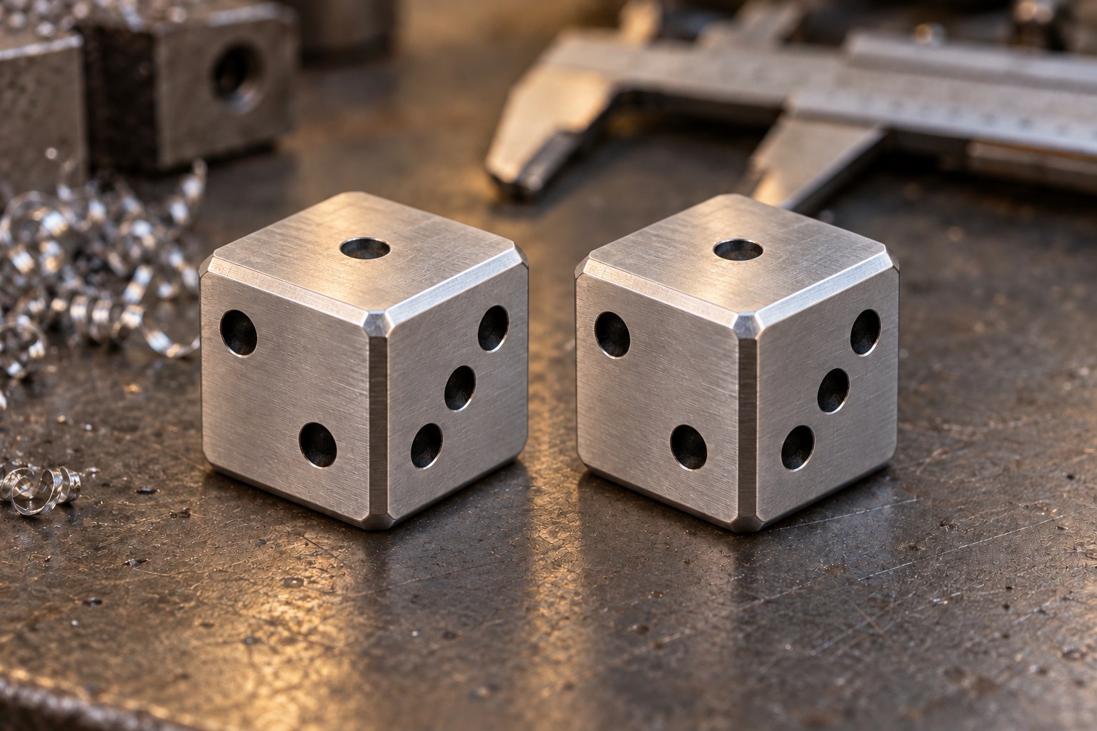
Two scraps of aluminum. Twelve faces. Forty-two little pockets. An entirely unreasonable amount of pride.
There is a special kind of shop brain that looks at a perfectly good plastic die and thinks, “I could spend my entire Saturday making that out of metal.” That brain is welcome here.
A matching pair of CNC dice is a great excuse to turn two offcuts into something you can actually put on the table at game night. It also packs a surprising amount of machining into one cube: squareness, workholding, repeated setups, small features, edge finishing, and the eternal question of where your zero went.
About the pictures: The three images are AI-generated concepts created for this article. They illustrate a proposed aluminum dice project, rather than documenting a completed shop build.
Start with a cube that deserves the name
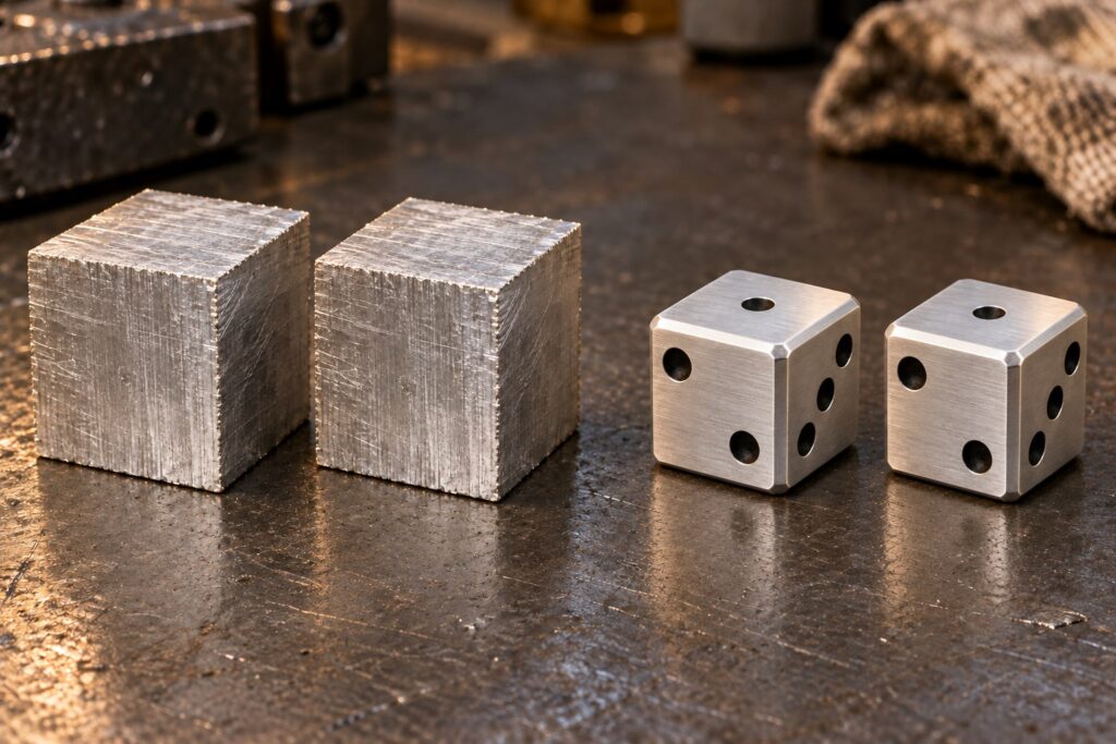
For this concept, picture two matching finished dice around 20 mm across. Start with two oversized blanks so there is material to clean up. Saw-cut faces are a starting point; the mating and locating faces need attention before they become your reference surfaces.
Make the finished dimensions consistent in all three directions and keep neighboring faces square. A cube that rocks on the bench has already invented its own game mechanic.
Keep the CAD model simple: one cube, a modest consistent edge chamfer, and a repeated pip feature. Decide the pip diameter, depth, and spacing once. Reuse those choices on every face instead of eyeballing each new setup.
Count the dots before cutting the metal
The traditional six-sided layout puts 1 opposite 6, 2 opposite 5, and 3 opposite 4. Every opposite pair adds to seven, as described by Wolfram MathWorld.
| Face | Opposite face |
|---|---|
| 1 pip | 6 pips |
| 2 pips | 5 pips |
| 3 pips | 4 pips |
Our chosen corner has 1 on top, 2 on the left visible face, and 3 on the right visible face. The hidden opposite faces are 6, 5, and 4 respectively. Both finished dice use that same layout. Draw a face map before you start rotating each blank. Mark the orientation somewhere that will not become a finished feature. You do not want to discover two sixes after the last setup and call it “a custom luck upgrade.”
Tiny parts need grown-up workholding
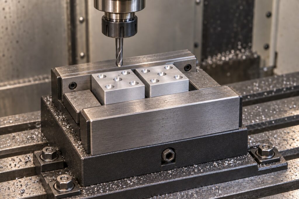
Each little cube needs support, sufficient jaw engagement, and a tool path that clears the vise. In the setup concept, both cubes sit between a fixed rear jaw and movable front jaw. Support beneath the parts and flat locating faces make the intended setup easier to understand. Clean chips from the seating surfaces whenever you reposition it.
Use jaw geometry appropriate to the part and operation. Leave enough of the top face accessible for the pip pattern, then check the cutter and holder clearance against the actual jaws. The picture shows the pair together, but two parts in one vise require matched gripping dimensions and verified secure seating for each part. Machine them individually when the setup cannot grip both reliably. A ball-nose cutter can make shallow rounded recesses; confirm that the chosen tool and toolpath produce the intended shape.
Sandvik Coromant’s milling guide emphasizes rigid clamping, stable workpiece support, and short practical tool reach. Those basics matter just as much when the finished part fits between two fingers.
A sensible sequence for the matching pair
- Model and map it. Establish the final cube size, edge treatment, pip pattern, and opposite-face pairs.
- Square the blank. Create clean reference faces and bring the cube to its intended dimensions.
- Plan each orientation. Keep a face map for each cube. Decide what seats against the jaws and supports, and how you will establish the work offset after repositioning.
- Cut one face at a time. Verify the active face and pip count before running each operation. A three-axis mill can approach the six faces through separate setups.
- Check the complete setup in CAM. Include the stock, jaws, and other fixture geometry. Review approach moves, retracts, tool reach, and clearance for every orientation.
- Finish and inspect. Deburr the pip edges, apply the planned chamfers, and check dimensions and face layout before adding any color.
Choose cutting data for your actual material, cutter, and machine using the toolmaker’s guidance. The fun part is the project; the feeds and speeds still have to belong to your setup.
Make it look like it was on purpose
A consistent brushed finish and small edge breaks can make the cube feel much more finished. Recessed pips can stay bare or receive a contrasting infill after machining and cleaning. For the illustrated design, silver aluminum and black pips keep the numbers easy to read.
Uniform-looking features do not prove that a homemade die rolls fairly. Treat it as an experiment or novelty piece until you have evaluated its behavior. Also give metal dice a suitable rolling tray—your dining table did not volunteer to become a test coupon.
Side quests for the shop goblin
- Match the pair’s dimensions, pip patterns, and finish; the second die deserves the same attention as the first.
- Give the pair a fitted little storage pocket in an offcut.
- Add initials somewhere that does not make the pip count confusing.
- Keep a setup sheet so the second die does not consume another entire Saturday.
That is the charm of a small shop project: the finished object is tiny, but the lessons are real. At the end, you have a matching pair, a better feel for repeated setups, and a completely defensible reason to rescue another aluminum offcut.
Roll for initiative. Measure for everything else.